 |
Shaanxi FKS Electronic Parts Import & Export Co.,Ltd.Xixian New Area FKS Electronic Technology Co.,Ltd. |
|
||||||
The working principle and function of the inductor
The working principle and function of the inductor
Magnetic antenna coils in radios, high frequency choke coils in simple semiconductor radios, oscillating coils in superheterodyne radios, etc. are all inductors. Inductors, commonly known as inductance coils or simply coils, are also a commonly used electronic component; but their applications in circuits are much less than that of resistors and capacitors. So what exactly is an inductance? What role can it play in the circuit? Let's take a look:

1. Definition
Inductor is a component that can convert electrical energy into magnetic energy and store it. It is a device made according to the principle of electromagnetic induction. In fact, any device that can produce self-inductance and mutual inductance can be called an inductor. Inductors are widely used. In AC circuits, inductors have the ability to hinder the passage of AC. They are often used in circuits as blocking, voltage transformers, AC coupling, and loads. When inductors are matched with capacitors, they can be used for tuning. , filtering, frequency selection, frequency division, etc.
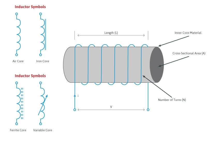
The simplest inductor is to use a wire to wind a few times in a hollow core, and an inductor with a magnetic core is wound a few times with a wire on the magnetic core. No matter what kind of inductor, if the structure is the same, its basic characteristics are the same, but the inductance of the inductor is different when the number of turns is different or the magnetic core is different. The more turns of the winding, the greater the inductance. Under the same number of turns, the inductance will increase after adding a magnetic core to the coil.
Inductors have inductive reactance characteristics in the circuit. The inductive reactance blocks the flow of current like resistance, but the inductive reactance is related to the frequency of the current flowing through the inductor, and is also related to the inductance of the inductor itself. The inductance is a path for DC, but it has a great hindering effect on AC. Usually we call it inductive reactance, XL=2πfL, where XL is the inductive reactance of the inductor; f is the frequency of the alternating current flowing through the inductor; L is the inductance of the inductor quantity. Under the premise that the inductance is determined, the larger the f is, the larger the inductive reactance is, that is, the greater the hindering effect.

电感器外形
2. Working principle
When a current passes through a wire, a concentric magnetic field is generated around the wire. At this point, if you bend the wire into a "spring shape" as shown in the picture, the magnetic flux inside the inductor will point in the same direction, increasing it. By adjusting the number of turns, a magnetic field proportional to the number of turns can be generated. This is the principle of inductors.
A current passing through an inductor will generate a magnetic field, and conversely, a change in the magnetic field will generate a current.
(Law of Electromagnetic Induction)
E = L ・(d i/d t)
L: Self-inductance of the inductor
E: Back EMF
The back electromotive force E generated in the inductor is proportional to the rate of change of the current per unit time (di/dt), so it does not occur when a certain current continues to flow in the same direction as a direct current. That is to say, the inductor has no effect on the DC current, and only acts as a blocker for the AC current. Using this property of an inductor, it can be used as a resistance (impedance) in an AC circuit. The impedance Z (in Ω) of the inductor is:
Z=ωL=2πfL
f is the AC frequency and L is the self-inductance of the inductor.
3. Symbols and units
(1) Inductance symbol: L
(2) Inductance unit: Henry (H), millihenry (mH), microhenry (uH), 1H=103mH=106uH.
(3) Nominal of inductance: straight standard, color ring standard, no standard
(4) Inductance directionality: no direction
(5) Check the quality of the inductance method: use an inductance measuring instrument to measure its inductance; use a multimeter to measure its on-off, the ideal inductance resistance is very small, almost zero.

4. Main technical parameters
①Inductance: Also known as self-inductance coefficient (L), it is a physical quantity that expresses the self-induction capability of an inductive element. The unit of L is H (Henry), mH (millihenry) and μH (microhenry). The conversion relationship between the three is as follows:
1H = 103mH = 106μH
②Quality factor: It is a parameter indicating the quality of the inductor coil, also known as the Q value or the figure of merit. The higher the Q value, the lower the losses in the circuit and the higher the efficiency.
③Distributed capacitance: There are capacitances between the turns of the coil, between the coil and the ground, between the coil and the shielding box, and between the layers of the coil. These capacitances are collectively referred to as the distributed capacitance of the coil. The existence of distributed capacitance will increase the equivalent total loss resistance of the coil and reduce the quality factor Q.
④Rated current: refers to the maximum working current that is allowed to pass through the coil for a long time.
⑤Stability: It mainly refers to the degree to which the parameters are affected by temperature, humidity and mechanical vibration.
5. Function
(1) Blocking: The self-induced electromotive force in the coil is always opposed to the current change in the coil. It can be mainly divided into high frequency choke coil and low frequency choke coil.
(2) Tuning and frequency selection: The inductance coil and the capacitor are connected in parallel to form an LC tuning circuit. That is, the natural oscillation frequency f0 of the circuit is equal to the frequency f of the non-AC signal, and the inductive and capacitive reactance of the loop are also equal, so the electromagnetic energy oscillates back and forth between the inductor and the capacitor, which is the resonance phenomenon of the LC loop. During resonance, since the inductive reactance of the circuit is equal to and opposite to the capacitive reactance, the inductive reactance of the total loop current is the smallest and the current is the largest (referring to the AC signal of f=f0), so the LC resonant circuit has the function of selecting the frequency and can An AC signal of a certain frequency f is selected.
(3) Choke: It is used to prevent low-frequency alternating current in low-frequency circuits; pulsating direct current to pure direct-current circuits; it is often used in the middle of two filter capacitors at the output end of the rectifier circuit, and the choke coil and capacitor form a filter circuit. In high-frequency circuits: It is to prevent high-frequency current from flowing to the low-frequency end, and high-frequency choke coils in old-fashioned regenerative radios are used.
(4) Filtering: It is also to prevent the rectified pulsating DC current from flowing to the pure DC circuit. The choke coil (in order to simplify the circuit and reduce the cost, use pure resistance instead of the choke coil) and two capacitors (electrolytic capacitors) form a filter circuit. Using the capacitor charging and discharging function and the choke coil to pass the direct current to block the alternating current characteristic to complete the smooth direct current and obtain the pure direct current.
(5) Oscillation: Rectification is to convert alternating current into direct current, then oscillation is the inverse process of converting direct current into alternating current, so the circuit that completes this process is called "oscillator". The waveform of the oscillator: there are sine wave, sawtooth wave, trapezoidal wave, square wave, square wave, and peak wave. The frequency ranges from a few hertz to tens of gigahertz. It is widely used in wired and radio fields.

6. Detection
Common faults of inductors are open circuit, short circuit, etc. In order to ensure the normal operation of the circuit, the inductor must be measured before use. The ohmmeter of the multimeter can be used to perform a simple measurement of the inductor, and the DC resistance of the inductor coil can be measured and compared with its technical indicators: if the resistance value is higher than the specified resistance value If it is much smaller, it means that the coil has a partial short circuit or a serious short circuit; if the resistance value is ∞, it means that the coil has an open circuit.
7. Precautions for use
(1) When using inductance
Humidity and dryness, ambient temperature, high-frequency or low-frequency environment, and whether the inductor should express inductive or impedance characteristics, etc., should be paid attention to.
(2) Frequency characteristics of inductors
At low frequencies, inductors generally exhibit inductive characteristics, which only store energy and filter high frequencies. But at high frequencies, its impedance characteristics are obvious. There are phenomena such as energy consumption and heating, and the reduction of perceptual effects. Different inductors have different high frequency characteristics.
The above is the introduction of the definition, working principle, symbol and unit, technical parameters, precautions of use and function of the inductor in the circuit. There are many types of inductors. According to different structural characteristics, they can be divided into single-layer coils, multi-layer coils, honeycomb coils, coils with magnetic cores and variable inductance coils, etc. Requirements and other conditions to decide.
【 Go Back 】 | 【 Print 】 | 【 Close this window 】


